
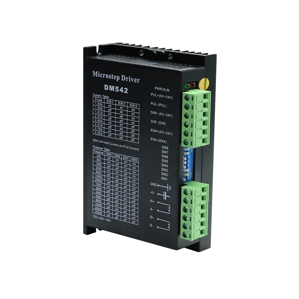


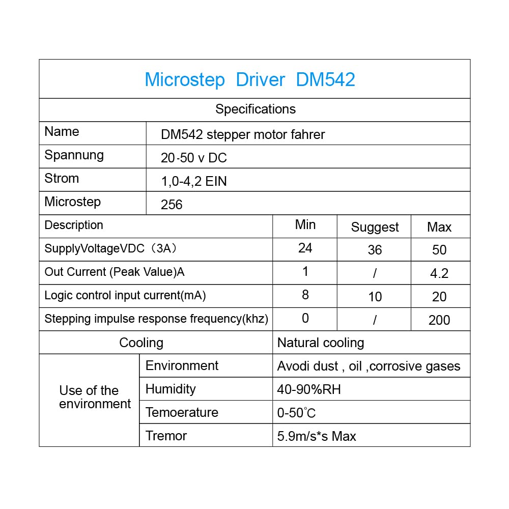
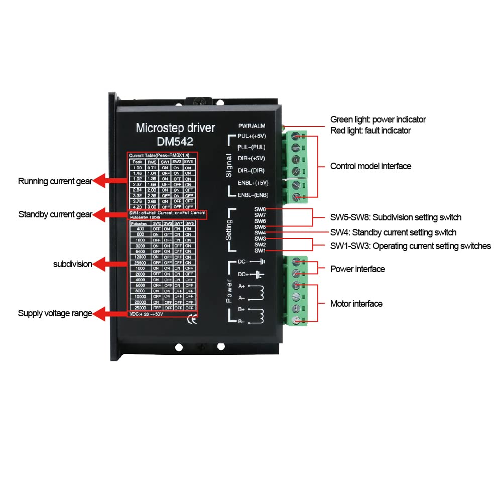
1. Electrical parameters: Input voltage: DC 24~50V input Output current: less than 4 amperes Output current: 1.0A~4.2A Power consumption: power consumption: 80W; internal insurance: 6A Temperature: working temperature -10~50℃; storage temperature -40℃~70℃ Humidity: no condensation, no water droplets Gas: non-flammable gas and conductive dust Weight: 250 grams 2. Control signal interface: 1. Definition of control signal PLS+: Step pulse signal input positive terminal or positive step pulse signal input positive terminal PLS-: Step pulse signal input negative terminal or positive step pulse signal input negative terminal DIR+: Step direction signal input positive terminal or reverse step pulse signal input positive terminal DIR-: Step direction signal input negative terminal or reverse step pulse signal input negative terminal ENA+: Offline enable reset signal input positive terminal ENA-: Offline enable reset signal input negative terminal When the offline enable signal is valid, the drive fault is reset, any valid pulse is prohibited, the output power element of the drive is turned off, and the motor has no holding torque 2. Control signal connection The control signal of the host computer can be effective at high level or at low level. When high is effective, connect the negative ends of all control signals together as the signal ground, when low, connect the positive ends of all control signals together as the signal common end. Now take the open collector and PNP output as an example, the interface circuit diagram is as follows: Drive wiring: A complete stepper motor control system should contain stepper drives, DC power supplies and controllers (pulse sources). The following is a typical system wiring diagram:
Trustpilot
3 weeks ago
1 week ago